General description
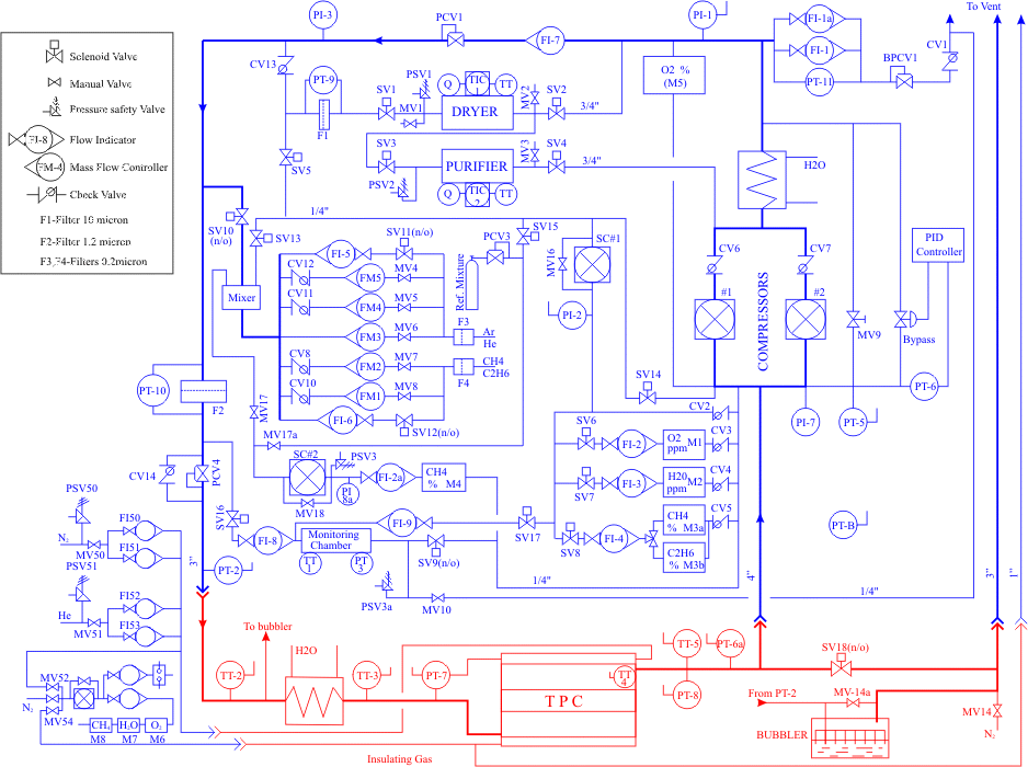
The primary purpose of the STAR TPC GAS System (see gas diagram below) is to provide either of two pure gas mixtures, P10 or helium + 50% ethane, to the TPC at the correct temperature and pressure. A secondary function of the system is to cool the outer field cage resistor strings located in two channels at the top of the drift volume. The system operates nominally as a closed circuit gas system with the majority of gas recirculating through the TPC and delivery system. During normal operation a small amount of fresh gas is added and an equivalent quantity of the existing mixture is vented. The gas system can be operated in an open system configuration for purging TPC.
 Gas system diagram.
The gas circulation rate is 36,000 l/hr which, given the volume of TPC is 50 cubic meters, gives one volume change every 1.4 hours. The gas system contains two compressors, one active and one spare, each capable of 60,000 l/hr at 100 mbar gauge. This pressure is reduced to 30 mbar by the first pressure regulator and then to 2.4 mbar by a second regulator upstream of the TPC. A water cooled heat exchanger downstream of the compressors is used to remove the compression heat.
The return gas manifold is maintained at 1.6 mbar above atmospheric pressure with a differential pressure transmitter and pneumatic controller that operates a bypass valve. A second bypass valve is manually adjusted to enable the automatic control loop to be used within its optimum range.
Part of the gas mixture passes through the monitoring chamber that continuously monitors the variation of parameters (mixture temperature, absolute pressure and mixture composition) which affect the TPC output. Data from the monitoring chamber is compared against pre-measured reference values and corrections are applied to correct shifts in the system.
Gas is admitted to the system between the 30 mbar and 2.4 mbar pressure regulators. The quantity of fresh mixture may be 0.6 to 6.0% of the total flow, i.e. 3.6 to 36 l/min. Simultaneously, the same amount is removed from the system using a back pressure regulator installed downstream of the compressors and set to maintain a pressure of 100 mbar. Fresh gas input is regulated by the mass flow controllers in the helium (argon) and ethane (methane) supply lines. These units are normally remotely controlled by computer but may be controlled locally if necessary. Manual valves and flow indicators, in parallel with the mass flow controllers, are used to fill and/or purge the TPC.
Part of the recirculating flow can be directed through a purifier and/or dryer connected to the “high pressure”, 100 mbar, section of the supply via solenoid valves. All gas passing through either unit also passes through a 20 micron filter before returning to main flow. All gas, recirculating and fresh, passes through a fine, 0.45 micron, filter before entering the TPC. The purity and composition of the TPC gas is monitored using oxygen, ethane (methane) and humidity analyzers.
As a backup to the primary pressure control, a second, dual set point, pressure transducer (PT-5) on the return manifols will sound an alarm if the pressure falls below 0.5 mbar. Once the pressure falls below the set point, the transducer will stop the compressor and admit make-up gas. A second 0 mbar gauge set point will perform these same functions should the first switch closure fail. This transducer functions through the DAQ and Control system. A dual set point pressure indicating switch (PI-7) on the return manifold will also stop the compressor and admit fresh gas if the pressure falls below 0.5 mbar, independent of the Control system. Thus the system is equipped with two separate units to prevent the TPC field cage from experiencing an external over pressure.
An alarm system is installed to warn of any fault conditions and to take corrective actions automatically if specified limits are exceeded. These actions include stopping the gas system and cutting off the high voltage to the TPC. A computer is included for data acquisition and to provide a feed back loop to control the gas mixture composition. In addition, all analyzers, mass flow controllers, monitoring chamber output and instruments are read and archived by the computer. These values can be selected and viewed on the terminal.