Time Expansion Chamber / Transition Radiation Detector
General Description
The primary purpose of the TECs/TRDs Gas System (see gas diagram below) is to provide P10 (Ar+10% Methane) pure mixture to the TECs at the correct temperature and pressure. Gas system parameters are as follows:
| Detector volume | 11 800 litres |
| Mixture | Ar + (10 ± 0.1%) Methane |
| Compressor pressure | 90 – 100 mbar |
| Internal detector pressure | 0.40 ± 0.01 mbar |
| Return pressure | 0.15 ± 0.01 mbar |
| Recirculation flow | 6 000 l/h |
| Flow through detectors | 2 400 – 4 000 l/h |
| Purge flow | 4 000 l/h |
| Fresh mixture | 1- 20 l/min |
| Oxygen content | < 20 ppm |
| Water content | < 15 ppm |
The system operates nominally as a closed circuit gas system with the majority of mixture recirculating through the TECs and delivery system. During normal operation a small amount of fresh mixture is added and an equivalent quantity of the existing mixture is vented. The gas system can be operated in an open system configuration for purging.
 Gas system diagram.
The mixture circulation rate through the compressor is 6000 l/hr and 2400-4000 l/hr through the TECs . The gas system contains two compressors (A,B), one active and one spare, each capable of 12500 l/hr at 100mBar gauge pressure. The 100 mBar output pressure from the compressor is reduced to 10mBar by the pressure regulator (PCV1) and supported with the back pressure control valve (BPCV2). A water cooled heat exchanger (HE2) downstream of the compressors is used to remove the compression heat. The return gas manifold is maintained at 2.0mm WC above atmospheric pressure by a differential pressure transmitter (PT3) and pneumatic (PID) controller that operates a bypass valve. The bypass shunts flow from the compressor discharge line directly back to the compressor’s inlet. A second bypass valve (MV3) is manually adjusted to enable the automatic control loop to be used within its optimum range. The bypass line including the manual valve (MV8) and back pressure control valve (BPCV2) gives a possibility to the smooth gas system start and the rapid response on the increased or reduced Methane content measured with the Methane analyzer upstream of compressor. Also, it permits to prepare the mixture with a homogeneous Methane content.
Two flow indicators (FI1 and FI2) will measure the recirculating flows: main and bypass. A difference between of them is the flow through the TECs. The measurements of the fresh mixture (FM1,FM2) and flow through the flow indicator (FIB) give a possibility to estimate the detectors leakage. The purity and composition of the mixture is monitored using oxygen, methane and humidity analyzers. A fraction of the recirculating mixture can be passed through a purifier and dryer to remove moisture and contaminants as needed.
A computer driven data acquisition/control system monitors all of the process variables. The computer system flags quantities which fall outside of predefined limits and initiates corrective action. However, where the safety of equipment or personnel are affected, a relay based, hard-wired interlock system connected to redundant set of sensors control the action of all key based controls fail.
It is imperative, for the safety of the decides, that the TECs inside pressure accurately track barometric pressure. A rapid change in atmospheric pressure is typical preceding storms and hurricanes. To assure that the TECs follow a fast rise in atmospheric pressure, a relatively large flow of inert gas will admitted into the vessels in the event that normal pressure controls fail to keep up with "falling" internal pressure. The vent lines and associated valves are sized to allow for rapid venting of the TECs mixture to prevent a high internal pressure in the case of the fast barometric pressure fall. The blower will reduce the pressure drop along the vent line too. In addition the bubblers connected to the TECs return manifolds will vent in the event that all other measures fail.
Pressure Control
There are two sources of pressure in the system, the first is the compressors located at the exit of the TECs. The second is the flow of fresh mixture through the mixing manifold. Nominally the pressure within the TECs is controlled by maintaining a constant pressure upstream of the TECs via the pressure reducing regulator (PCV1) plus back pressure regulator (BPCV2) and varying the pressure downstream of the TECs by regulating the amount of mixture shunted from the compressor output to inlet. On a longer time scale the flow of fresh mixture is constant.
The output from the compressor is 6000 l/hr at 100 mBar. a back pressure regulator (BPCV1) in the outlet line is set to 100 mBar thus maintaining a maximum delivery pressure independent of the compressor output. This pressure is reduced to 10 mBar by the pressure regulator (PCV1) and supported with the back pressure regulator (BPCV2) upstream of the TECs. The TECs exhaust pressure, measured at the return gas manifold is maintained at 2.0 mm WC by a TESCOM electropneumatic PID controller. A 0-2.5 mm WC differential pressure transmitter (PT3) on the return manifold produces a 4-20 mA output that the PID controller compares to a set-point value. If the transmitter signal is different from the setpoint the controller sends a pneumatic output signal to the bypass control valve. the bypass shunts flow from the compressor discharge line directly back to the compressor’s inlet. opening the bypass valve causes the TECs exhaust pressure to rise and closing the valve makes the pressure fall. A second bypass valve (MV3), manually adjusted during the initial system set-up, enables this automatic control loop to be used within its optimum range.
The fresh mixture is admitted between the pressure regulator (PVC1) and back pressure regulator (BPCV2). The quantity of fresh mixture may be changeable in the range of 1.0-20l/min with the mass flow controllers (FM1 and FM2). To purge the detectors the quantity of fresh mixture can be increased up to 100 l/min by using the flow indicators (FI3 and FI4). Simultaneously, gas is removed from the system through the back pressure regulator (BPCV1). To have the stable content of fresh mixture the Argon mass flow controller (FM3) operates the Methane one (FM4). It means that FM3 is a master and FM4 is a slave. These units are normally locally controlled. The quantity of fresh mixture are monitored with PC data acquisition/control system.
When the internal TECs pressure, as measured by PT2 and PI1, is more then 2.5 mm WC above the atmospheric one, the gas control system will close the solenoid valve (SV3) in the fresh mixture supply line and open the vent line valves (SV21, SV22) allowing mixture to vent directly to the atmosphere. But if the vent line pressure measured with the pressure indicator (PI5) will exceed 0.5 mm WC a blower will be turned on to reduce the vent line pressure. Also, a pressure indicating switch (PI1) has a set-point of 2.5 mm WC and it can operate SV3, SV6 and SV21, SV22 as the computer control and alarm systems. When the TECs and supply manifold pressure measured with the pressure transmitters (PT5,PT6) will be more than 15 mm WC or exit pressure measured by PT7, PT8 will be more 4 mm WC the gas control system will close SV3 and open SV21, SV22. Should the exit pressure reach 5.0 mm WC, the exit TECs mixture will vent to the atmosphere through the bubblers (B1,B2). With this arrangement the TECs are protected from either flow controller malfunction, a rapid drop in atmospheric pressure and/or a failure of the back pressure regulator.
In the event of a rapid rise in atmospheric pressure, or effectively a fast drop in the TEC’s internal pressure (up to 6 mBar/min), a dual set point Dwyer differential pressure transmitter (PT2) in the return manifold will trip as the pressure falls below 0.5mm WC causing an audible and visual alarm. When the pressure at PT2 falls below atmospheric (0 gage) a second set-point trips and the computer control system and also, the interlock/ alarm system will stop compressor, shut-off the flow of Methane , HV and pass inert gas by opening solenoid valve (SV6) to supply an additional 90 l/min of inert gas.
A pressure indicating switch (PI1) with dual set points is also installed in the return manifold. This switch is not connected to the computer control system and alarm system but instead is hardwired to perform the same functions as computer and interlock/alarm systems in the event of a falling TECs pressure. Thus the system is equipped with three separate means of preventing the TECs from experiencing an external over pressure.
In the case of detectors leakage the flow direction indicators (FDI1,FDI2 ) will show which detector has the leak and the computer control system and/or alarm system will stop the flow through the detector by closing the input and output solenoid valves, tern off the HV.
In the event of a power failure, the solenoid valves SV6,SV7,SV3, SV16-17, SV19-22 will open, or remain open and SV8, SV9 will close, causing 90 l/min of inert gas to flow through the TECs. This flow rate is adequate to assure that fluctuations in the atmospheric pressure will not result in the creation of over or negative pressure inside the TECs. If the one detectors arm will be connected at the assembling hall to the gas system, the solenoid valve (SV27) will be opened to have the same pressure as the second detectors arm at the beam area.
Temperature Measurement
Four temperature transmitters (TT1, TT2, TT3, TT4) are used to measure the mixture temperature within the TECs. A fifth temperature transmitter (PTM) measures the mixture temperature within the monitoring chamber. The data of measured mixture temperature are logged for later use in data reduction.
Mixture Control
Along with automated valve control, the gas system’s dedicated computer controlled data acquisition provides constant monitoring of the mixture composition vie measuring the mass controllers output signals. Methane analyzer will be used periodically to check Methane content in the mixture. The mixture ratio is fixed by the Teledyne mass flow controllers (FM1, FM2) with the inert gas "slaved" to the Methane flow controller. The stability of the flow controllers is sufficient to make variation in the mixture negligible.
Gas Sampling
The gas system is equipped with Oxygen, Moisture and Methane analyzers plumbed such that each section of the gas system can be selected separately for evaluation. All analyzers data are read and archived by the computer data acquisition system and used to control the gas system.
Gas Purification
A mixture dryer and purifier withdraws a portion (about 15 l/min) of the reciculating flow upstream of the pressure regulator (PCV1) and delivers the conditioned gas to the recirculating flow downstream of PCV1. This loop is used only as needed. The dryer is made from the a stainless steel tube containing 3 lbs of molecular sieve(zeolite 13X) as adsorbent. This amount permits the removal of about 1 lbs of water vapor to a level 2-3 ppm at room temperature. Filters are installed upstream and downstream of the adsorbent to prevent particles from entering to the mixture stream. A heating element is placed inside the dryer. As the thermal insulation a vacuum insulation is used.. The dryer is regenerated by heating to 350-400 C with purging of Argon. The purge gas enters at the top of the dryer and exits at hte bottom carrying with it the water vapor. A temperature transmitter installed inside the dryer is connected to the temperature controller (TIC2) that supports the dryer temperature on the set-pointed level. A moisture analyzer is used to measure the quantity of the water in the circuit before and after the dryer to determine when the adsorbent is saturated.
The purifier is similar to the dryer except that it is filled with a catalyzer that permits the oxidization of C by Oxygen, present as an impurity, to form alcohol. The alcohol is subsequently removed by the dryer. The catalyzed oxidization process takes place at 220 C that is supported with the temperature controller (TIC1). A heat exchanger (HE1) is used to reduce the mixture temperature coming into the dryer. This purifier does not require regeneration but must work in conjunction with the dryer. Solenoid valves (SV1 and SV2) installed at the inlet and outlet of the purification loop isolate the unit from the main circuit when it does not in use. If the inside pressure of purifier/dryer will be more than 5 PSI the solenoid valve (SV2) works as the safety valve and prevents the purifier/dryer from a damage. A 10 micron filter is installed after the purifier/dryer to prevent dust from passing into the main mixture supply line. A differential pressure transmitter (PT4) is used to check the filter’s plugging.
Computer Control and Data Acquisition
The gas system includes a computer driven data acquisition and control system. The controlling computer is a dedicated PC running Windows 2000. It reads the data and operates the gas system via KEITHLEY 7001 high density switch system that can accommodate up to 80 channels of 2-pole switching and KEITHLEY 2000 Digit Multimeter. This computerized system is programmed to acquire the signals from the various temperature, pressure, flow and content measuring devices and issue warnings and/or take corrective action in the event that predetermined levels are exceeded. All acquired values can be selected and viewed on the terminal. There is a possibility to look the gas system parameters using World Wide Web. The control software was developed using Borland Delphi and is almost identical with TEC/TRD, MuID and STAR TPC software.
Interlock/Alarm System
A microprocessor driven interlock/alarm system is installed to warn of fault conditions and to take corrective action automatically if specified limits are exceeded. These actions include stopping the gas system compressor, flammable gas flow and shutting off the high voltage to the TECs and TRDs. The interlock/alarm system is parallel and, in many cases, redundant to the computer control system but it directly reads the gas system parameters and takes the action immediately if specified limits are exceeded the set-pointed level.
Additional figures and schemes
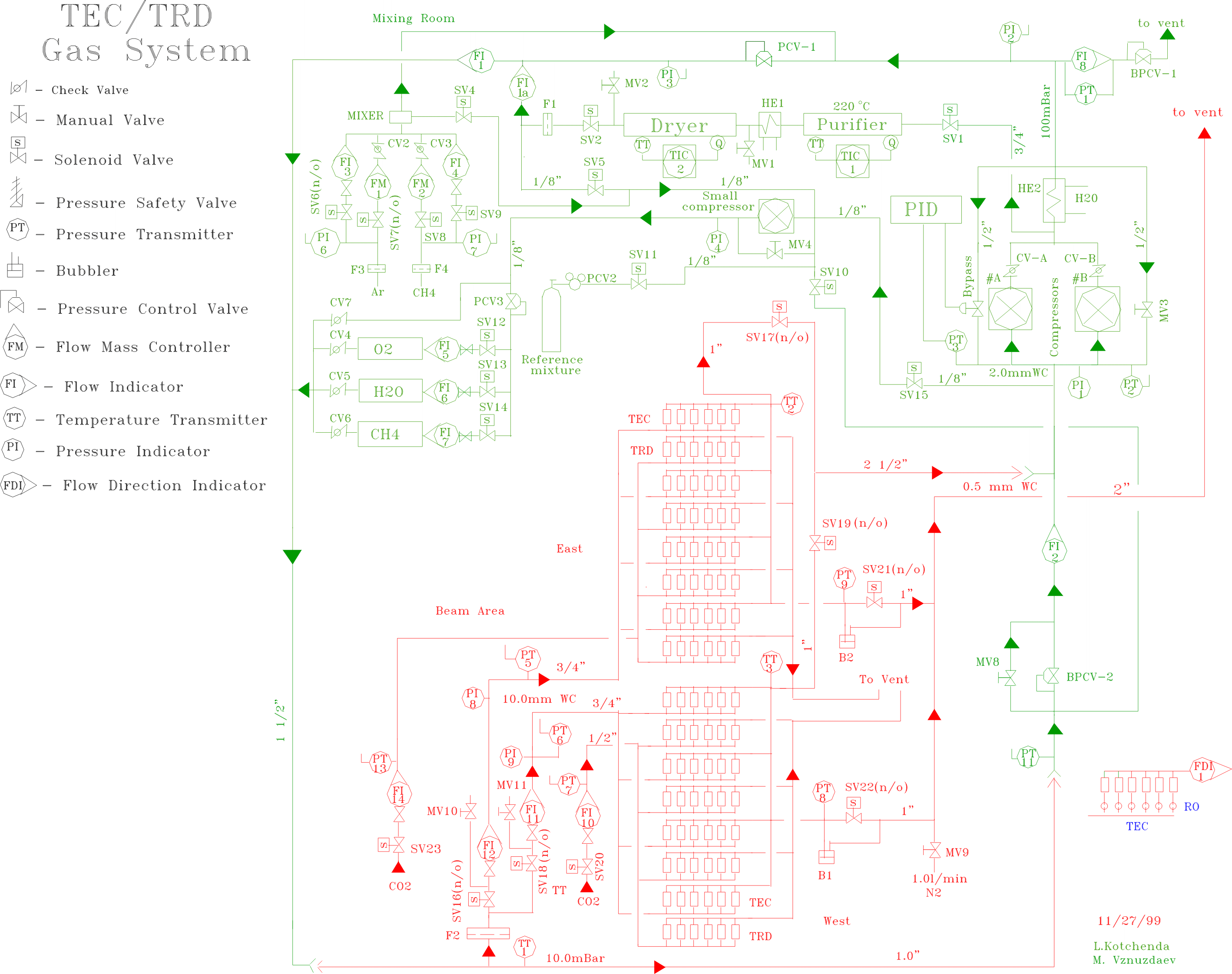 Gas scheme
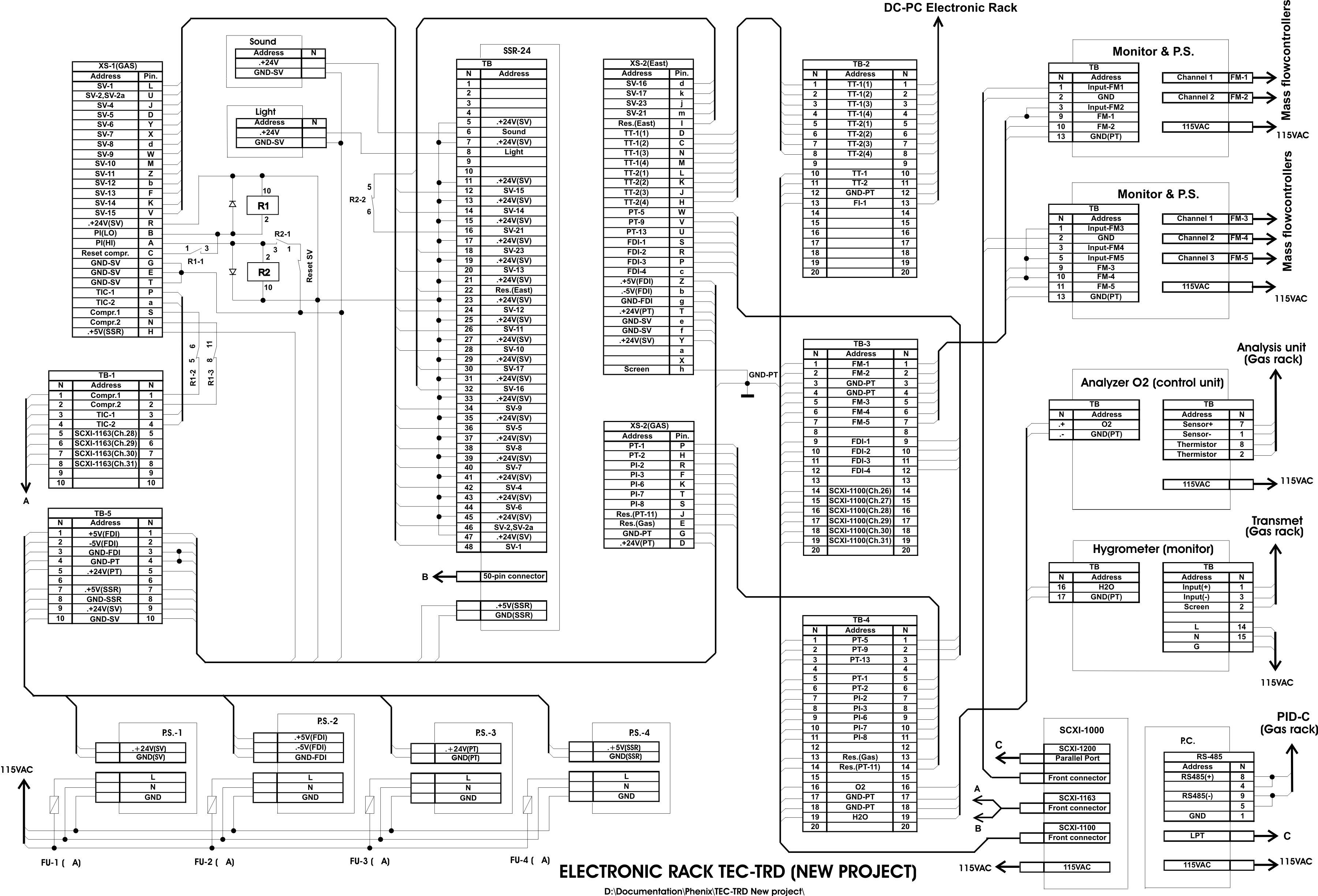 Electronic rack wiring diagram
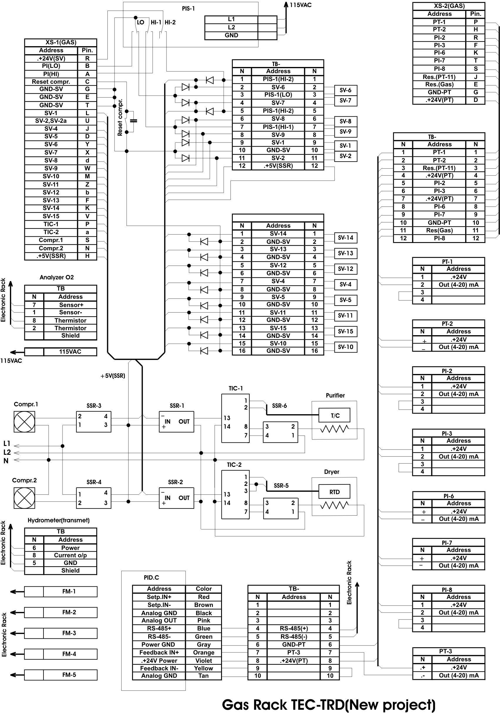 Gas rack wiring diagram
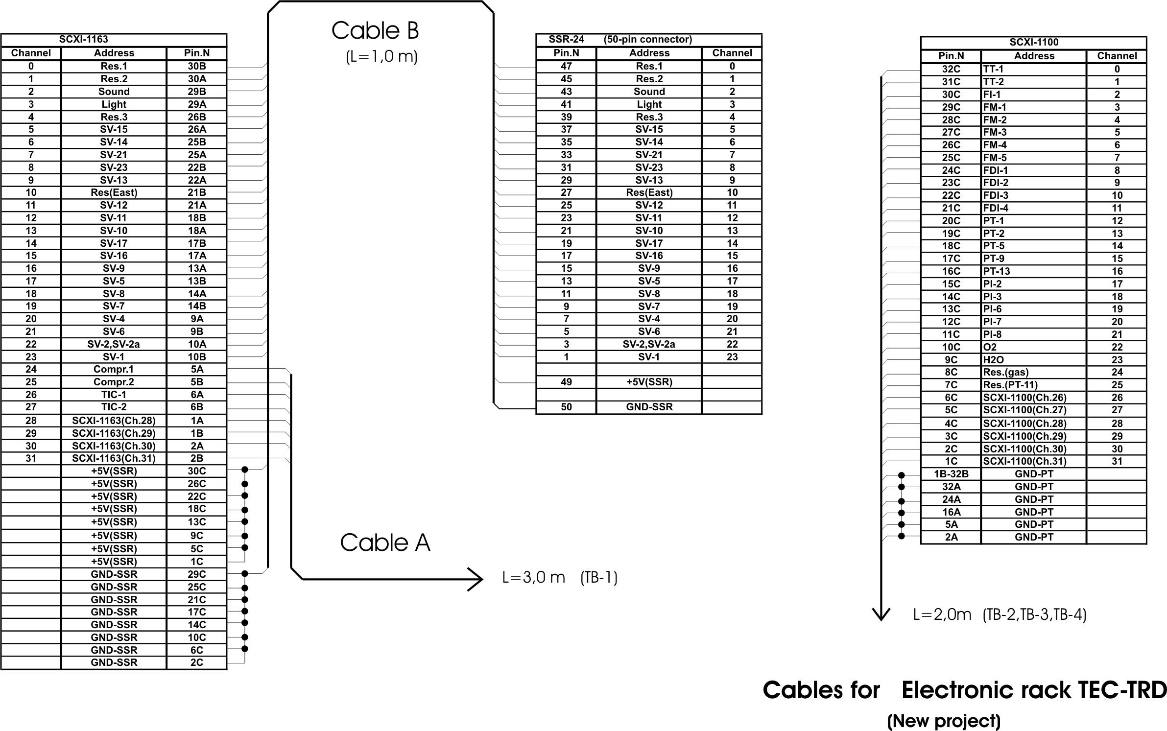 Cables wiring diagram
 Gas system software manual
DBViewer manual
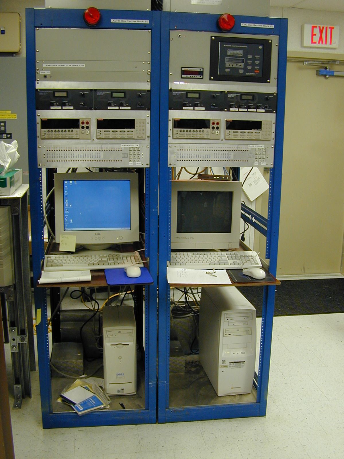 Electronic rack photo (DC/PC + TEC/TRD)
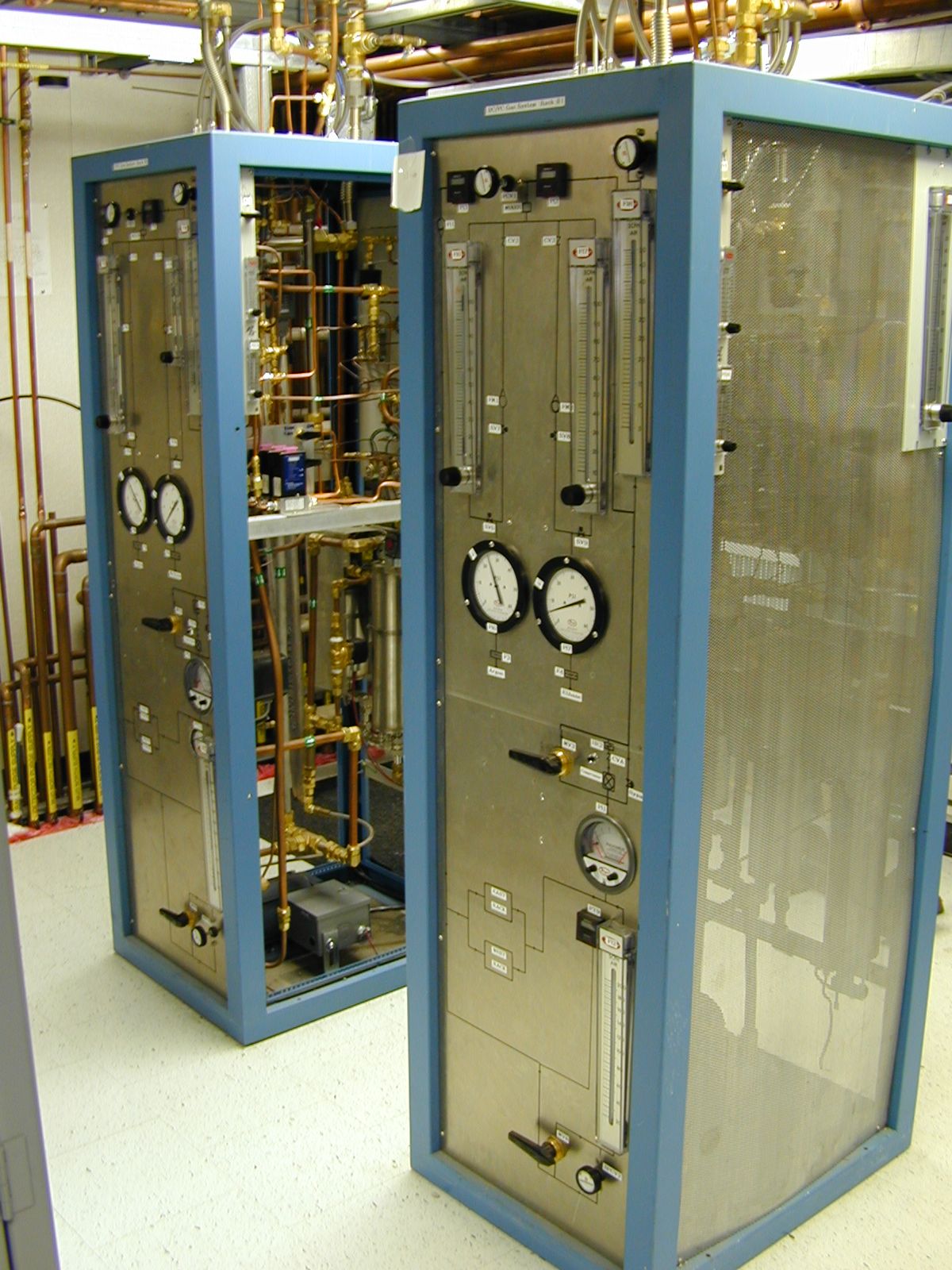 Gas rack photo (DC/PC + TEC/TRD)