PC software and alarms configuration
Alarm System provides reliable RS-232 data exchange in order to change alarms configuration and reading system status. The software for PC is developed for Windows platform. The window of this program has four tabs: one for reading Alarm System status, second for configuring alarms, third for Analog Inputs test, and fourth for valves configuration.
In order to make alarms setup easier, the software operates real valve names and properties. This information may be changed on "Valves" tab. For each valve user can set name and type of valve (or device): normally closed or normally open. For devices open state means turned on while closed state means turned off. All information can be stored in registry or saved/loaded into/from binary file.
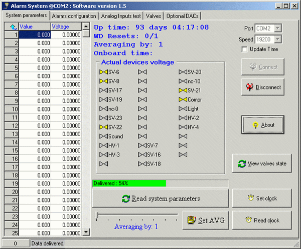
The "System parameters" tab includes small communication setup. User must select COM port connected to Alarm System. The speed of data exchange is always set to 19200b/s. Program will not communicate with Alarm System without connecting to appropriate COM port. If program detects an Alarm System connected to specified port, it displays internal software version of this system. Port will be automatically disconnected in 10 seconds if no Alarm System observed on this port. The "Read system parameters" button reads Alarm System status information. It updates the following parameters:
- Up time – the time since last power-up,
- WD resets – watch-dog counter, number of WD resets since last power-up (total resets counter since last maintenance is displayed after slash – 1 means the only service reset),
- Onboard time (for the devices with Dallas Time-keeping NVRAM only),
- Averaging by – number of analog signal samples to average by,
- Valves state – current state of all devices connected to Alarm System,
- Physical values and voltages of analog signals.

System parameters window
The "Valves and devices state" box may be used to manual control each particular device, but will not affect devices, activated by an alarm. Actually it changes the DEFAULT state, so be careful with this control. Current DEFAULT state will be shown in this window, if one reads system parameters of total blocked (code 79) Alarm System, because in this case actual state of all digital outputs is the same as in the DEFAULT state.
Besides, user can change averaging number using a trackbar at bottom of the window and "Set AVG" button. This value will be taken into account in the next alarm handling cycle. Time required for one 32-channel cycle as function of averaging number for 11.0592 MHz crystal is given in table below. For the 22.1184 MHz cycle time is twice less.
| Average by | Alarm cycle time, ms |
| 1 | 22 |
| 2 | 30 |
| 4 | 42 |
| 8 | 68 |
| 16 | 120 |
| 32 | 220 |
| 64 | 420 |
| 128 | 800 |
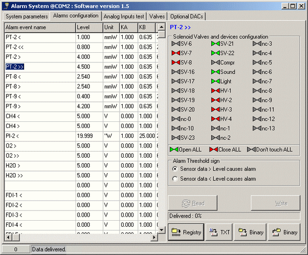
The "Alarms configuration" tab is used to configure alarms and actions to be taken in case of any particular alarm. For every alarm user is able to change:
- Alarm event name – this string is used only in the PC program for better understanding what this alarm is used for, instead of numbers in Alarm System
- Level – alarm threshold. Exceeding this threshold analog signal value causes an alarm
- Unit – only in PC program, units of physical value of this analog signal
- KA – A coefficient for calculating physical value from voltage. PC only
- KB – B coefficient for calculating physical value from voltage. PC only
- Devices configuration – alarm action, see further description
- Alarm threshold sign – alarm comparison sign

Alarm configuration window
Alarm names, physical value units, coefficients are intended to appear only in PC program. Voltage is calculated from physical value by the formula: , where S is physical value, V – voltage, KA and KB – coefficients.
Solenoid valves and devices configuration allows one to customize the alarm action. If an alarm occurred, the red valves will be closed and red devices will be turned off. Green valves will be open, green devices will be turned on. Gray valves and devices will not be affected in case of this particular alarm. For example, in the valves configuration showed on Fig. 4, SV-1 and SV-2 will be closed, SV-4 will be open while all other valves will not be affected, i.e. their state will be intact.
"Read" button downloads current alarm configuration from Alarm System, "Write" button uploads it to Alarm System. Note that COM port should be open before these operations. User can save current configuration to Registry (it is done automatically when window closes), save and load it to/from binary file. Besides, "TXT" button exports alarm configuration to text file as table with alarms in rows and valves state in columns, which can be extremely useful for analyzing in MS Excel to see the whole configuration of all the alarms on one page.