Introduction
The objective behind the Alarm System was to create a reliable control system that will operate gas system and take some actions in case of certain alarm conditions. This device is now being used in TEC/TRD, DC/PC and STAR TPC gas systems as a fast interlock system and in ATLAS CSC gas system as DAQ and control electronics for the computer control software. It is rather flexible and can be used in wide range of experiments.
The Alarm System is based on Atmel 89C52 microcontroller running at an 11.0592 MHz (22.1184 MHz) clock frequency. It has 8Kb non volatile RAM to keep the alarms configuration and the status information there. Analog signals from the sensors go through two 16-channel multiplexers and instrumentation amplifier to 12-bit ADC, which can be replaced by 16-bit one. CPU takes care of handling these signals, comparing them to alarm thresholds, and sets corresponding digital output signals via four 3-wire registers. In order to block some alarms a keypad is used. All triggered and blocked alarms are indicated on two lines LED indicator. There is a supervisor watch-dog on this board, which attends to 8051 program faults and resets CPU as fast as in 0.8 s in this case. Alarm system can be connected to PC via standard RS-232 port.
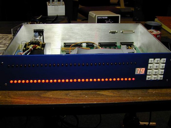
Alarm system front view
To change blocking of any particular alarm one should enter the number of this alarm (01 32) and press [*] button on keypad, while [#] button unblocks current alarm. One can block or unblock all alarms together by entering "79" as alarm number and pushing [*] or [#] button (Total Blocking).
During tests and measurements Alarm System appears to be very reliable and stable device. For instance, system had been worked over months with no watchdog resets, i.e. no internal software faults. Flexible alarm action configuration gives one a possibility to use it not only for gas system, but also in any project that requires simple and fast interlock system. The main features of the Alarm system are:
- 32 analog input channels with 16-bit resolution
- 32 digital output channels (transistor switches)
- RS-232 interface at 19200 baud (38400 baud at 22.1184 MHz crystal)
- Separate and total alarm blocking from keypad on front panel
- 11 ms minimal response time (without averaging at 22.1184 MHz crystal)
- Flexible alarm actions configuration for each particular alarm
- System information available via RS-232, including watchdog resets counter, up time, analog values and digital output status
- Analog inputs test mode for choosing convenient averaging number
- Power consumption: 15 mA for 12 V and 250 mA for 5 V with all LEDs lighted