Muon TRacker
General Description
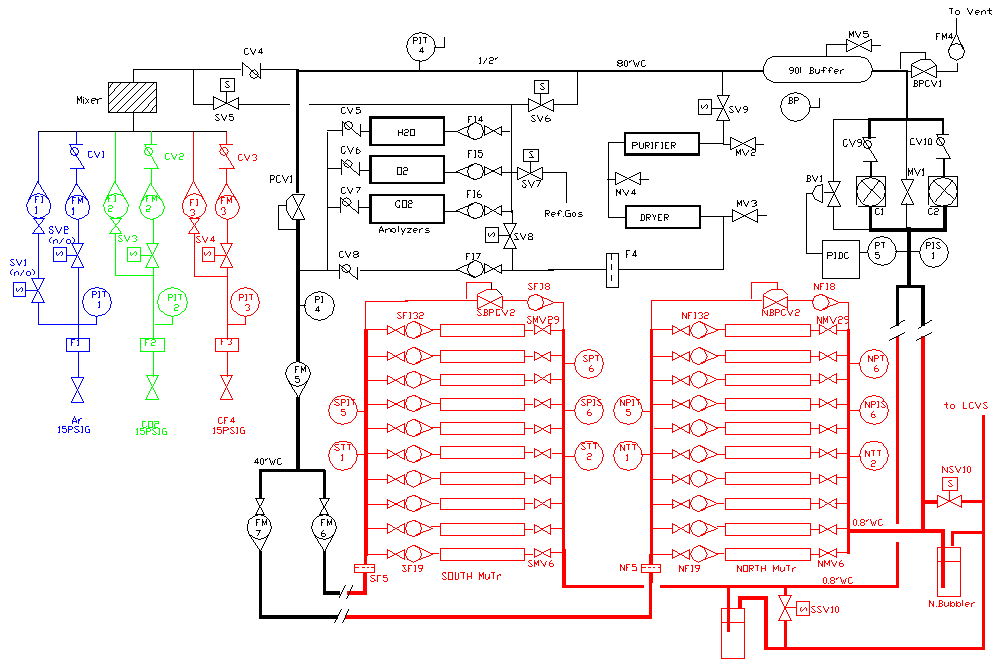
The primary purpose of the MuTr Gas System (see gas diagram below) is to provide Ar+30%CO2+20%CF4 pure mixture to the MuTr chambers (North and South arms) at the correct pressure. Gas system parameters are specified in the table below.
| Detector volume | xxx litres |
| Mixture | Ar+30%CO2+20%CF4 |
| Compressor pressure | 100 – 200 mbar |
| Mixture supply pressure | 100 mbar |
| Mixture return pressure | 2 mbar |
| Recirculation flow | 300 – 900 l/h |
| Purge flow | 60 l/h |
| Fresh mixture | 0- 0.2 l/min |
| Oxygen content | < 200 ppm |
| Water content | < 80 ppm |
The system operates nominally as a closed circuit gas system with the majority of mixture recirculating through the MuTr. During normal operation a small amount of fresh mixture is added and an equivalent quantity of the existing mixture is vented. The gas system can be operated in an open configuration for purging
The mixture circulation rate through the small membrane compressor is 15LPM at 80”WC. The gas system contains two compressors(C1,C2), one active and one spare. The mixture from the compressor goes to the supply line through the check valves CV9 and CV10. The 80”WC output pressure from the compressor is reduced to 40”WC by the pressure regulator (PCV1) and supported with the back pressure control valve (BPCV1). The return gas manifold is maintained at 0.8”WC above atmospheric pressure by a differential pressure transmitter (PT5) and pneumatic (PID) controller that operates a bypass valve. The bypass shunts flow from the compressor discharge line directly back to the compressor’s inlet. A second bypass valve (MV1) is manually adjusted to enable the automatic control loop to be used within its optimum range.
 Gas system diagram.
The mass flow indicator FM5 will measure the recirculating flow. The measurements of the fresh mixture (FM1,FM2 and FM3) and flow through the mass flow indicator (FM8) give a possibility to estimate the detectors leakage. Two mass flow indicators (FM6, FM7) will measure the recirculating flows: North and South MuTr arms.
The purity and composition of recirculating mixture is monitored using oxygen, carbon dioxide and humidity analyzers. A fraction of the recirculating mixture can be passed through a purifier and dryer to remove moisture and contaminants.
A computer driven data acquisition/control system monitors all of the process variables. The computer system flags quantities which fall outside of predefined limits and initiates corrective action. However, where the safety of equipment or personnel are affected, a relay based system connected to redundant set of sensors control the pressure levels of all key based controls fail.
A rapid change in atmospheric pressure is typical preceding storms and hurricanes for BNL area. To assure that the MuTr chambers follow a fast rise in atmospheric pressure, a relatively large flow of inert gas will admitted into the chambers in the event that normal pressure controls fail to keep up with “falling” internal pressure. The vent lines, associated valves and bubblers are sized to allow for rapid venting of the MuTr chambers mixture to prevent a high internal pressure in the case of the fast barometric pressure fall.
Computer Control and Data Acquisition
The gas system includes a computer driven data acquisition and control system. The controlling computer is a dedicated PC running Windows 2000. It reads the data and operates the gas system via SCXI data acquisition and control system. The solenoid valves, compressors, light and sound are controlled by PC through the SCXI and solid state relay board. This computerized system is programmed to acquire the signals from the various temperature, pressure, flow and content measuring devices and issue warnings and/or take corrective action in the event that predetermined levels are exceeded. All acquired values can be selected and viewed on the terminal. There is a possibility to look the gas system parameters using World Wide Web. The control software was developed using Borland Delphi and is almost identical with TEC/TRD, MuID and STAR TPC software.