Cooling system for Lambda wheels silicon detector
In the collaboration of Nationaal Instituut voor Kernfisica en Hoge-Energiefysica (NIKHEF) Amsterdam, The Netherlands, Department of Physics II, University of Erlangen-Nuernberg, Germany and Petersburg Nuclear Physics Institute the Silicon-Detector system for the HERMES front region was developed. Two wheel shaped arrays of silicon strip detectors are placed in between the down-stream end of the storage cell and the vertex chamber. The cooling system for the detector was designed and produced in PNPI.
 Operation temperature of the detector defined by two factors:
- The absorption of hydrogen (there is the flux of hydrogen from the storage cell) diminishes with temperature;
- Leakage current due to radiation is lower at lower temperatures.
On base of these considerations the operational temperature has been chosen to be 25°C. Cooling system is designed for the wide range of the temperature: +20°C – 40°C, allowing an optimization of this temperature during the experiment.
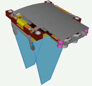
The detector itself consists of twelve identical modules. A module (which covers 30°C) is built from two parts (see figure) and each includes itself a silicon detector (1) and the carrier board for the electronics to process the signals from the detector (2). The silicon wafers mounted in a light frame made out of aluminum (3). The heavy bars (4) are connected to the cooling ring.
 Cooling system for the Silicon Detector is compatible with the ultra-high vacuum of the accelerator. The system (see two layout figures) consists of two loops. The closed internal loop transports heat from the silicon detector to the cooling system. The open external loop (1) takes heat from the internal loop and transports this to the external water lines (2). The heat pump between the internal loop (which operates at low temperature) to external one, consists of Peltier modules (3). The heat flow is controlled by the current through Peltier modules which gives us the possibility to stabilize the temperature of detector. The elements of the system is placed in the different areas:
- In the ultra high vacuum area we have part of the internal loop and the cooling rings which transfers the heat from silicon wafers and carrier boards (4) to the internal loop.
- In a low vacuum area the main part of the cooling system is located. In this area we have Peltier modules (3). The heat exchangers between the internal and external loops (5) are located here, as well as the circulating pump of the internal loop (6) and the temperature sensors (7) for the cooling system. One way ball valve in the internal loop (8) is necessary for the filling-evacuation procedure of the liquid from the internal loop. Heater gives us a possibility of the fast heating of the system to the room temperature and for the overheating to the 40 C for the fast outgasing. Level detector (10) controls the quantity of the liquid in the internal loop. For the internal loop we use the ethyl alcohol with the high purity 99.9%.
- Outside, in the atmosphere we have vacuum insulated drive (11) for the snake pump, bellow (12) for the pressure normalization in the internal loop, valves structure with the manometer for the filling-evacuation procedure.

The main tasks of the control system for the cooling are:
- stabilizing the average temperature of the detectors;
- reading information from the temperature sensors on the carrier boards;
- checking the alarm situations;
- data passing to the central slow control system.
The microprocessor system (based on the Intel 87C51 processor) has been used. Analogue board collects information from all the temperature sensors and the processor board works with this information and takes a decision about temperature stabilization and the alarms. Processor board has a serial interface RS232C for the communication with the central slow control system.
The main characteristic of the cooling system is the possible minimum temperature at every level of the heat power consumption. For this test we used the module imitators with onboard heater and temperature sensor. The water at 10°C has been used as a heat sink for these tests (see figure below).
At the temperature -25°C we can take from the electronics about 30W of power, which is sufficient for the work (2W per module – nominal heat flux).
See also
![]() Software channels description.
Software channels description.
