Structure
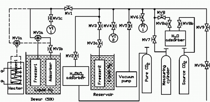
The system (Fig. 1) consists of 40-liter Measuring cylinder, block of drying (H2O adsorber), multifunction block of fine drying and purification from oxygen (H2O & O2 adsorber), 2-liter freezers (Freezer1 and Freezer2), adsorption vacuum pump (Adsorber), mechanical roughing-down pump with the liquid nitrogen trap (Vacuum pump), electric heater (Heater), 50-liter Dewar, Reservoir for liquid nitrogen, manual operating valves (MV1-9a), exemplary manometer M1, ionization vacuum gauge VI1 and mechanical vacuum gauge VI2.
 Fig.1. Schematic diagram of CO2 Purification System.
Source gas (Source CO2) is being delivered in 40-liter steel cylinders. Refined gas is being accumulated in 40-liter stainless steel cylinder (Pure CO2). It’s possible to divide the scheme on two parts. On the right of the valve MV6 a preliminary preparation subsystem (dosing and drying) is shown. On the left of MV6 valve the subsystem of deep purification is situated.
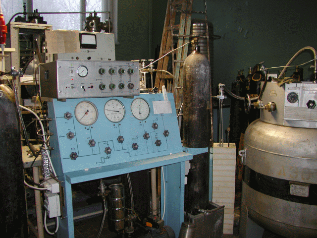
 Fig.2. CO2 Purification System.