Control and Data Acquisition
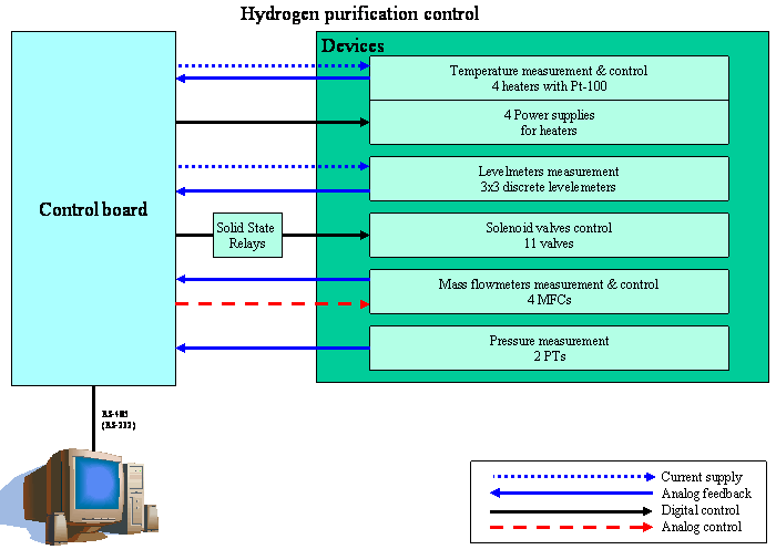
Control hardware consists of a PC and a specially designed control block, which provide all sensors interfaces and low-level control procedures. Automatic control of the system is carried out by microprocessor controller. Adjustment of the controller is executed by an operator through PC with the help of special software (Fig. 5).
 Fig. 5. Schematic diagram of CHUPS control.
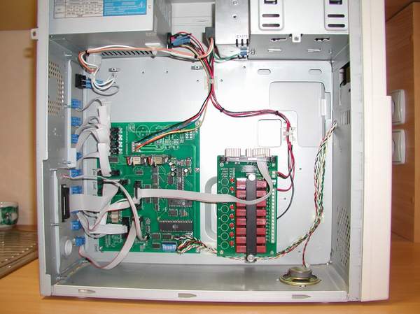
All solid state relays together with control board are installed in the control block (Fig. 6). A standard ATX PC case is used for the control block. Levelmeters, pressure and temperature sensors, flowmeters, heaters and valves control signals are connected at the rear side of the control block. Control board is designed to use either external power (from ATX power supply) or internal onboard power supply. Separate power supply is used for the solenoid valves control. Besides, there is a possibility to connect LED or LCD display to the control board to show current status of the system.
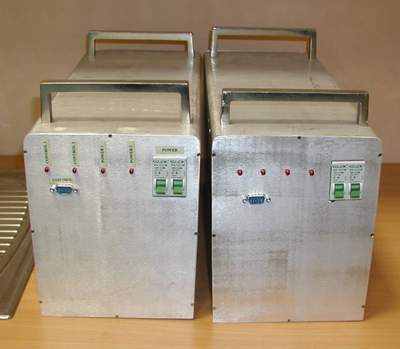
Heaters power supplies are based on the power transformers and have maximum power of 1000W each at 24VAC output voltage. They are assembled in two boxes (Fig. 7). Each power supply is controlled by a solid state relay and automatic circuit breaker. All of them are equipped by the input (220VAC) and output (24VAC) filters in order to avoid high power pulses influence to surrounding electronics. They also have minimum LED indicators to check current status of the powe supplies.
Control connectors, indicators and circuit breakers are mounted at the front panel of the power supplies while all input and output power connections are at the back side.
 rear side
