Power supply
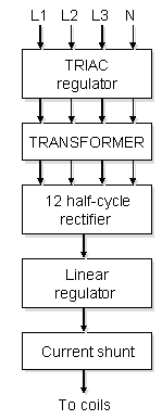
 Current supply (Fig. 3) uses 3-phase power. High efficiency is achieved by using two levels of current stabilization. First, control board roughly cut down 3-phase power by triac PWM regulator based on the Atmel AT89C2051 microcontroller. Power restriction setpoint comes from main CPU. Second, fine adjustment of output current is made after rectifier by a linear regulator making use of power MOSFET transistor. Control signal for this transistor is generated from the current shunt signal and control signal from 16 bit DAC.
The distinctive advantage of the power supply is so-called 6-phase two-halfperiod rectification of the alternating current. This allows to achieve output current modulation less than 1.5% at the maximum output current of 200 A. Ripple frequency is 600 Hz which is easily suppressed by LC-circuit. Primary windings of the power transformer are connected by a "star" scheme. Three secondary windings with N2 turns each are connected by a "star" scheme to the Larionov’s [1] rectifier. Another three secondary windings with N3=sqrt(3)*N2 turns each are connected by a "triangle" scheme to the second Larionov’s rectifier. Similar outputs of the both rectifiers are merged together. Both rectifiers are based on 3-phase diode bridges 160MT120KB (International Rectifier) with a maximum current of 160 A.
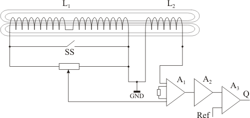
One of the most important elements of SCPS device is quenching detectors. They should detect spontaneous transitions of the coils from superconducting state to normal. The coupler loop is installed near each of the magnet. They are inductively coupled with the magnets. Main coil and coupler loop are connected to the bridge scheme in opposite directions. Differential signal in the bridge scheme is balanced by a trimmer (Fig. 4) and then comes to amplifier A1.

Fig. 4. Quenching detector.
There are three modes of operation:
- current injection to superconducting coils
- current removal from superconducting coils
- permanent operation with frozen current.
During the current injection superconducting switch (SS) is open. Voltage at the ends of coil L1 is proportional to current injection speed: ![]() .
.
For the coupler loop the voltage is: ![]() , where I1 – current through L1, M – mutual inductance factor.
, where I1 – current through L1, M – mutual inductance factor.
These voltages are summarized at the differential amplifier A1. The result will have different sign for current injection and removal. RMS to DC converter A2 is used to get absolute value of the signal, which then is compared with the threshold on the comparator A3. Threshold value is chosen to get required sensitivity at the typical current injection or removal speed. Quenching of the coil during current injection does not affect voltage of the coupler loop because current in the coil is supported by the source, but voltage of the main coil will be changed because of the voltage drop on the normal wire. This will cause change in the bridge signal which could exceed threshold value. Therefore comparatore will generate quenching signal Q processed by the main CPU. Quenching in frozen current mode is processed in a similar way.
All ballast resistors and power components like current shunt and MOSFET transistor are mounted on water-cooled heat exchanger. Temperature of this heat exchanger is measured by control board and produces overheating alarm.